In part 3 we saw how the VTX5000's 8K ROM is structured and how the BASIC program drives the terminal.
Now we'll look at the Z80 machine code that handles the real-time work: talking to the 8251 USART, managing the buffers, and scanning the keyboard with its Prestel-specific remapping.
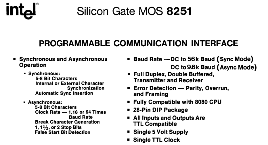
The Intel 8251
The 8251 has a bunch of bits that can be set for commands and configuration:
Command flags
| Bit | Mask | Name | Meaning when set |
|---|---|---|---|
| 7 | $80 | Hunt mode | In synchronous mode, enter hunt for SYN characters |
| 6 | $40 | Internal reset | Reset the 8251 state machine; the next byte is configuration mode |
| 5 | $20 | RTS | Assert RTS |
| 4 | $10 | Error reset | Clear parity, overrun and framing error flags |
| 3 | $08 | Send break | Force the TxD line low |
| 2 | $04 | Rx enable | Enable the receiver |
| 1 | $02 | DTR | Assert DTR |
| 0 | $01 | Tx enable | Enable the transmitter |
Configuration mode flags
| Bit(s) | Mask | Name | Values |
|---|---|---|---|
| 7-6 | $C0 | Stop bit length | 00 = invalid, 01 = 1 stop bit, 10 = 1.5 stop bits, 11 = 2 stop bits |
| 5 | $20 | Parity enable | 1 = parity enabled |
| 4 | $10 | Even parity select | 1 = even parity, 0 = odd parity |
| 3-2 | $0C | Character length | 00 = 5 bits, 01 = 6 bits, 10 = 7 bits, 11 = 8 bits |
| 1-0 | $03 | Baud rate factor | 00 = sync mode, 01 = 1x, 10 = 16x, 11 = 64x |
Status register flags
| Bit | Mask | Name | Function |
|---|---|---|---|
| 0 | $01 | Transmit Ready | High when the transmit buffer/register is empty and ready to accept the next data character from the CPU. |
| 1 | $02 | Receive Ready | High when the receiver has a character assembled and ready to be read by the CPU. |
| 2 | $04 | Transmit Empty | High in synchronous mode when the transmitter has no characters to send and the USART is sending sync characters. In asynchronous mode, it indicates the line has returned to the mark state. |
| 3 | $08 | Parity Error | High if the received data character does not match the parity selected by the mode instruction. |
| 4 | $10 | Overrun Error | High if the CPU does not read the previous character before the next one is received, causing data loss. |
| 5 | $20 | Framing Error | High in asynchronous mode if the stop bit of a received character is missing or invalid. |
| 6 | $40 | Sync/Break Detect | Indicates the detection of the sync character in synchronous mode, or a break condition in asynchronous mode. |
| 7 | $80 | Data Set Ready | Reflects the inverted status of the active-low DSR input pin from the modem or peripheral device. |
Hardware Initialisation
Before the modem can do anything, the 8251 needs to be initialized and the HW_INIT routine at $1424 does just that:
HW_INIT:
    LD A,$82            ; Hunt mode + DTR asserted
    OUT ($FF),A         ; Write to 8251 command register
    RES 5,(IY+$01)      ; Clear Spectrum's "new key" flag
    LD A,$40            ; Internal reset command
    OUT ($FF),A         ; Reset the 8251
    ; ... timing NOPs ...
    XOR A
    OUT ($FE),A         ; Set border to black
    LD A,(IX+$07)       ; Load configured mode register value
    OUT ($FF),A         ; Write mode to 8251
    LD (IX+$1B),$64     ; Set idle timeout to 100 (decimal)
At first glance this looks like it sets the 8251 into "hunt mode" via $82 which would use the shift register to find SYN bytes... BUT we're actually going to be using async so why do this? To flip the 8251 out of any pending state so that the $40 reset command that follows will work.
Once it sees that reset it knows the next byte will be the actual configuration from IX+$07 which is $7B for our async 7-bit data, even parity, 1 stop bit, 64× clock mode.
The IX Table
The IX register points to a table full of state and configuration the ROM uses extensively to save swapping registers a bunch.
| Offset | Default | Purpose |
|---|---|---|
+$00 | $C0 | Splash-screen tail byte (not used as IX data) |
+$01 | $03 | Splash-screen tail byte |
+$02 | $58 | Splash-screen tail byte ('X') |
+$03 | $02 | Buffer countdown (high byte) |
+$04 | $FF | Buffer size (255) |
+$05 | $00 | Unused / reserved |
+$06 | $60 | Device flags (bits 5+6 set at boot: TX busy + b6) |
+$07 | $7B | 8251 mode register: 7-bit data, even parity, 1 stop bit, 64× clock |
+$08 | $15 | 8251 command register: RxEn/TxEn/DTR, RTS=0 (VTX ROM paged in) |
+$09 | $00 | Keyboard / input state flags |
+$0A | $00 | Prestel frame parser state |
+$0B | $00 | Return code (0 = continue, 1 = BREAK, 2 = timeout, 3 = carrier lost, 4 = error, 5 = frame complete, 6 = retry, 7 = specific) |
+$0C | $00 | Cursor row |
+$0D | $00 | Cursor column |
+$0E | $00 | Last row rendered |
+$0F | $00 | Last column rendered |
+$10 | $00 | Previous line number (dirty-line tracking) |
+$11 | $00 | Display attribute state (low byte - EXX pair) |
+$12 | $47 | Display attribute state (high): bright white ink on black paper |
+$13 | $00 | Saved attribute state (low) |
+$14 | $00 | Saved attribute state (high) |
+$15 | $00 | Current display attribute |
+$16 | $00 | Unused / reserved |
+$17 | $00 | Saved attribute for restore |
+$18 | $00 | Previous keyboard scan result |
+$19 | $00 | Carrier-detect timeout (low) |
+$1A | $00 | Carrier-detect timeout (high) |
+$1B | $00 | Idle timeout counter (set to $64 by HW_INIT) |
+$1C | $FF | Prestel session scratchpad start |
+$2B | $FF | Prestel session scratchpad end |
+$2C | $00 | Prestel frame repeat count |
+$2D | $17 | Prestel line retry count (23) |
+$2E | $05 | Prestel attempt counter |
+$2F | $00 | Prestel data pointer (low) |
+$30 | $00 | Prestel data pointer (high) |
+$31 | $00 | Prestel shift state |
+$32 | $00 | Prestel parser flags |
+$41 | $05 | Prestel max attempts (5) |
+$42 | $64 | Online timeout (low) - $0064 = 100 |
+$43 | $00 | Online timeout (high) |
+$44 | $64 | Offline timeout (low) - $0064 = 100 |
+$45 | $00 | Offline timeout (high) |
+$46 | $20 | Character font base (low) - together = $1B20 |
+$47 | $1B | Character font base (high) - points at ROM font |
The Main Modem Loop
This is where the VTX5000 spends most of its time. It's a straightforward poll-and-dispatch cycle:
MODEM_MAIN_LOOP:
    LD (IX+$0B),$00      ; Clear return code
    CALL CHECK_TX_READY  ; Send a byte if transmitter is free
    CALL CHECK_RX_DATA   ; Read a byte if receiver has data
    LD B,$04
    CALL BUF_READ        ; Pull from RX buffer
    JR Z,.no_rx_data     ; Nothing? Skip processing
    CALL PRESTEL_DETECT  ; Check for Prestel frame markers
    CALL PROCESS_RX_CHAR ; Handle the received character
.no_rx_data:
    CALL SCAN_KEYBOARD   ; Check keyboard
    LD C,(IX+$0B)        ; Read return code
    LD A,C
    OR A
    JR Z,MODEM_MAIN_LOOP ; Code 0: keep looping
Every iteration, it checks for outgoing data, incoming data, and keyboard input. If a return code gets set anywhere (BREAK pressed, timeout, carrier lost, frame complete), the loop exits and returns to the BASIC program via USR. The return code in IX+$0B tells BASIC what happened - 0 means keep going, 1 is BREAK, 2 is idle timeout, 3 is carrier lost, and so on.
This cooperative polling design means nothing ever blocks. There's no interrupt-driven receive, no DMA - just a tight loop checking everything in turn, fast enough at 3.5MHz that nothing gets missed at 1200 baud.
Transmit
The transmit path is simple - check if the 8251's TxRDY flag is set, and if there's data in the TX buffer, send it:
CHECK_TX_READY:
    LD A,(IX+$06)
    AND $42              ; TX enabled?
    RET NZ               ; No: return
    IN A,($FF)           ; Read 8251 status
    BIT 0,A              ; TxRDY?
    RET Z                ; Not ready: return
    LD B,$02             ; Buffer type 2 (TX)
    CALL BUF_READ        ; Read from TX buffer
    RET Z                ; Empty: return
    CP $23               ; '#' hash?
    JR NZ,.not_hash
    LD A,$5F             ; Replace with underscore
.not_hash:
    OUT ($7F),A          ; Transmit byte
    RET
There's a character substitution here: the # key gets replaced with $5F (underscore) on transmit. This is a UK keyboard mapping artifact - on the Spectrum keyboard, what you'd think of as # needed to be sent as _ for Prestel's character set, where # has a different meaning (it's the "send" key in Prestel navigation, like pressing Enter on a form).
Receive
The receive side reads from the 8251 data register and writes into the RX buffer:
CHECK_RX_DATA:
    BIT 5,(IX+$06)       ; TX busy?
    RET NZ               ; Yes: skip RX
    IN A,($FF)           ; Read 8251 status
    BIT 7,A              ; DSR (Data Set Ready)?
    RET Z                ; No DSR: modem not connected
    LD (IX+$1B),$64      ; Reset idle timeout (modem is alive)
    BIT 1,A              ; RxRDY?
    RET Z                ; No data: return
    BIT 3,A              ; Parity error?
    IN A,($7F)           ; Read received byte
    JR Z,.no_parity_err  ; No error: use as-is
    LD A,(IX+$08)        ; Parity error: rewrite command register
    OUT ($FF),A          ;   (clears error flags)
    LD A,$FF             ;   Replace byte with $FF (error marker)
.no_parity_err:
    LD B,$04             ; Buffer type 4 (RX)
    CALL BUF_WRITE       ; Write to buffer
    CALL SET_CARRIER_TIMEOUT  ; Reset carrier timeout
    RET
A few things are worth noting.
- If the modem isn't reporting Data Set Ready, we don't even try to read. This is the VTX5000's carrier detect mechanism.
- Parity errors don't cause a crash or a disconnect - the errored byte is simply replaced with
$FFand passed on. The rendering engine will display something garbled, but the connection stays up. At 1200 baud over a phone line, occasional parity errors are a fact of life.
The idle timeout at IX+$1B is reset to 100 ($64) every time valid data arrives. It's decremented by the keyboard scan routine, and if it ever reaches zero, the return code is set to 2 (timeout). This is how the VTX5000 detects that the remote end has stopped sending.
The Buffers
There are two small buffers - type 2 for transmit, type 4 for receive - both embedded within the IX state block. Each buffer has a 2-byte count at its head, followed by the data bytes.
Write is trivial - increment the count, calculate the write position by adding count to the base pointer, and store the byte - this is basically a ring buffer:
BUF_WRITE:
    CALL BUF_GETPTR      ; Get buffer base and current count
    INC BC               ; Increment count
    LD (HL),C            ; Store count low
    INC HL
    LD (HL),B            ; Store count high
    ADD HL,BC            ; Point to write position
    LD (HL),A            ; Write byte
    RET
Read is more interesting - after reading the first byte, it shifts the entire remaining buffer down by one position using LDIR:
BUF_READ:
    CALL BUF_GETPTR      ; Get buffer base and count
    LD A,B
    OR C                 ; Empty?
    RET Z                ; Yes: return Z flag
    DEC BC               ; Decrement count
    LD (HL),C            ; Store new count
    INC HL
    LD (HL),B
    INC HL
    LD A,(HL)            ; Read first byte
    INC BC               ; Restore count for shift
    LD E,L               ; Set up LDIR (shift buffer down by 1)
    LD D,H
    INC HL
    LDIR                 ; Shift remaining bytes
    RET
This is technically a FIFO queue as there's no wrap-around, just a linear shift on every read. At 1200 baud with a buffer size of 16 bytes (when online) or 255 bytes (when offline), the LDIR is never shifting more than a few bytes, so the performance cost is negligible. It's a simpler implementation than a proper circular buffer with head/tail pointers, and on a system where RAM is scarce, every byte counts.
The BUF_GETPTR routine at $15F3 finds the right buffer by walking through the chain. Buffer type is passed in the B register, and the routine skips forward through the count/data pairs until it reaches the right one. It's a linked-list walk through what's essentially a stack of variably-sized buffers inside the IX state block.
Timeouts
Two separate timeout mechanisms protect against connection problems:
The idle timeout (IX+$1B, initialised to 100) counts down on each keyboard scan. Any received data resets it. If it hits zero, the return code is set to 2 ("Line Break" in BASIC). This catches the case where the remote end goes silent - no data, no carrier drop, just silence.
The carrier timeout (IX+$19/$1A, a 16-bit counter) uses different values depending on mode: 25000 cycles when offline and waiting for a connection, or a configured value when online. It's decremented on each keyboard scan, and if both bytes reach zero, the return code is set to 3 ("Carrier lost"). The SET_CARRIER_TIMEOUT routine picks the right values:
SET_CARRIER_TIMEOUT:
    LD L,(IX+$42)        ; Online timeout low
    LD H,(IX+$43)        ; Online timeout high
    BIT 0,(IX+$06)       ; Online?
    JR NZ,.set_timeout   ; Yes
    LD L,(IX+$44)        ; Offline timeout low
    LD H,(IX+$45)        ; Offline timeout high
    BIT 4,(IX+$06)       ; Auto-answer?
    JR NZ,.set_timeout   ; Yes
    LD HL,$61A8          ; Default: 25000
.set_timeout:
    LD (IX+$19),L
    INC H                ; Add 256 to high byte
    LD (IX+$1A),H
    RET
Keyboard Scanning
The keyboard scanner at $1550 does more than just read keys - it handles the translation from Spectrum's keyboard layout to Prestel's expectations.
The Spectrum keyboard uses a matrix read via port $FE. The scanner first checks for BREAK (CAPS SHIFT + SPACE), which sets return code 1 for an immediate exit. Then it reads the key value from the Spectrum's system variables (the ROM's interrupt handler has already decoded the matrix) and applies several transformations:
- Symbol Shift (
$0E) sets internal shift state flags - Prestel uses*(star) as a modifier key, so Symbol Shift is remapped to*for Prestel navigation - CAPS LOCK (
$06) toggles bit 3 of the border colour attribute - this gives visual feedback (bright/dim border) to show caps lock state, since Viewdata doesn't have a separate caps indicator - EDIT (
$07) toggles a display mode flag and triggers a full screen refresh - ENTER (
$0D) becomes$5F(underscore) - in Prestel, underscore is the "send" character - DELETE (
$0C) becomes$08(backspace)
The keyboard lock feature (bit 2 of IX+$06) suppresses all key output when set. This is used during data reception - Prestel doesn't support type-ahead, so keys pressed while a frame is loading should be discarded.
What's Next
In part 5 we'll tackle the Viewdata rendering engine and how it renders that 40x24 display with a 5-pixel font, mosaic block graphics and Prestel frames onto the Speccy's display.
0 responses